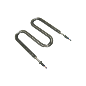
Tubular Heaters
Straight & Formed Tubular Heaters
Straight & Formed Tubular Heaters
Tubular heater are the main heating source in most applications where electric heat is required. They are highly adaptable to the requirements of many applications. Tubular heater can be used in their straight form or can be bent into various shapes. They can be used in free air, clamped to a surface, embedded, or cast into metals. Tubular heater can provide heat up to 1500°F.
Bucan tubular heater use 80% Nickel 20% Chromium high grade coiled resistance wire as a heating core. This core is welded at both ends to pins that provide a cold section that varies in length depending on the application requirements. The coil-pin assembly is precisely centred inside a heavy gauge, oversized metal tube, and embedded inside a 96% pure, high-grade MgO insulating medium. This assembly is then compacted through a roll-reducing process that reduces the outside tube diameter to its final size and transforms the MgO matrix into a rock-hard solid that acts as an excellent heat transferring medium, as well as an electrical insulation with high dielectric strength. Finally, heaters are annealed inside a high-temperature furnace to eliminate internal stresses accumulated during the cold-forming roll-reducing process to make them soft. Heating elements are then formed into special shapes or supplied in their straight form. Proper electrical terminations are added to the final product.
- Applications
- Specifications
- Selection
- Accessories
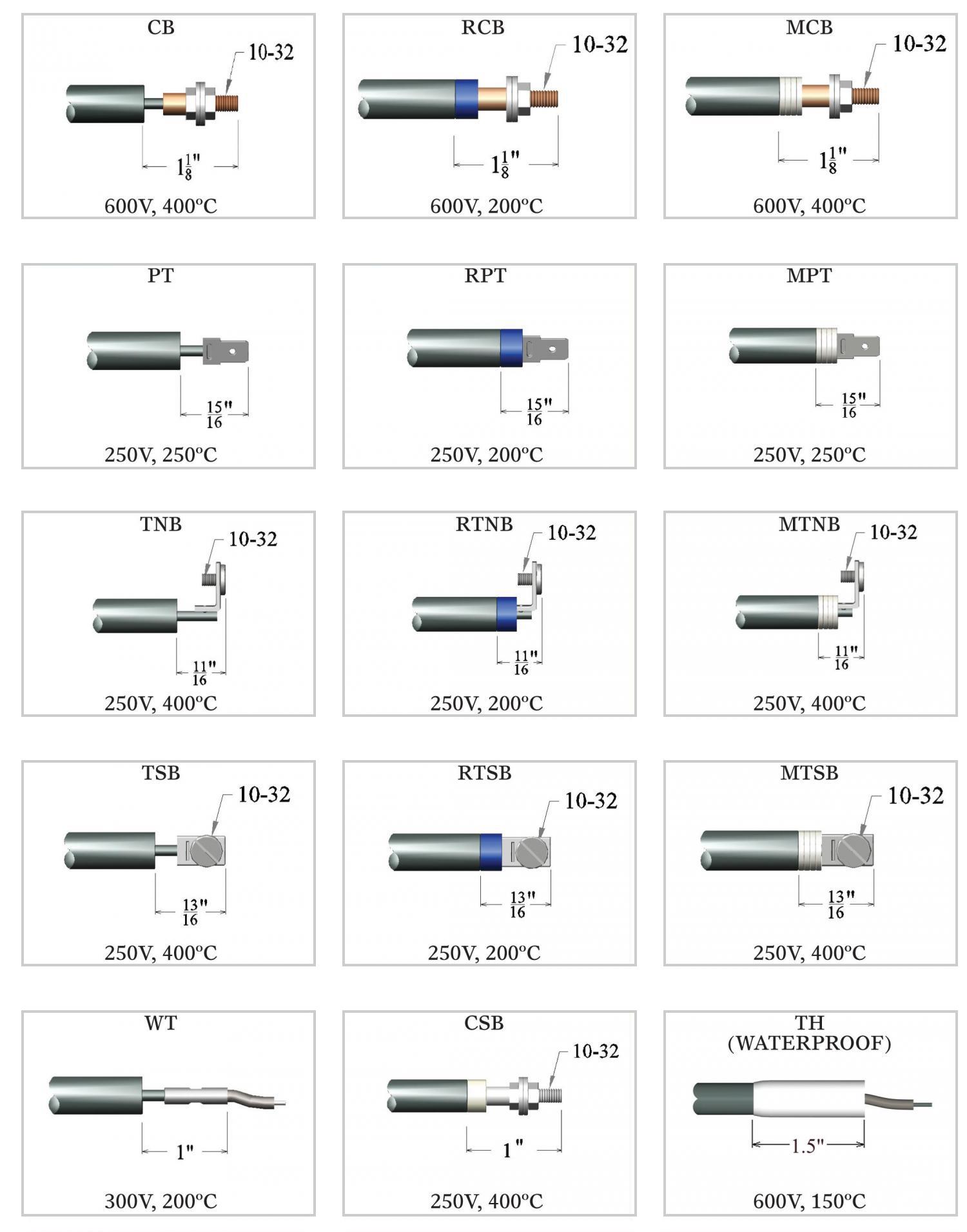
- Terminations
- Tips
- Moisture Proofing
Applications of Tubular heater
- FORMING MACHINES
- HEATING MOLDS & PLATENS
- IMMERSION INTO LIQUIDS
- RADIANT & CONVECTION HEATING
- EMBEDDED OR CAST INTO METAL
Specifications of Tubular heater
| Tubular diameter (inches) | Maximum voltage | Maximum amps | Minimum Ohms per heated length (inches) | Maximum Ohms per heated length (inches) | Minimum sheath length (inches) | Maximum sheath length (inches) |
| 0.260 | 240 | 15 | 0.1 | 17 | 11 | 240 |
| 0.315 | 300 | 30 | 0.06 | 20 | 11 | 240 |
| 0.375 | 600 | 30 | 0.05 | 20 | 11 | 240 |
| 0.430 | 600 | 40 | 0.05 | 20 | 11 | 240 |
| 0.475 | 600 | 40 | 0.05 | 20 | 11 | 240 |
| Overall length (inches) | 11-20 | 21-40 | 41-70 | 71-100 | 101-140 | 141-170 | 171-200 | 201+ |
| Tolerance in sheath length (+/- in) | 0.1 | 0.125 | 0.16 | 0.19 | 0.22 | 0.25 | 0.375 | 0.5 |
| Tolerance in heated length (+/- in) | 0.25 | 0.5 | 0.9 | 1.130 | 1.4 | 1.65 | 2 | 2.38 |
| Min. unheated length (inches) | 1 | 1.25 | 1.5 | 1.625 | 1.75 | 2.25 | 2.25 | 2.5 |

The two most critical factors that affect the durability of a tubular heater are:
- Sheath material
- Watt density
The corrosivity of the medium and its operating temperature are critical in determining the sheath material type. The table below lists various sheath materials, maximum allowable temperatures and mediums within which they are recommended to operate.
The watt density determines the temperature that a heating element sheath will attain within specific application conditions.
| Sheath Material | Maximum Sheath Temperature | Applications |
| Copper | 350°F | Immersion into water and non-corrosive low viscosity liquids |
| Steel | 750°F | Oil, wax, asphalt, cast in aluminum or iron |
| Stainless Steel 304-316 | 1200°F | Corrosive liquids, food industry, sterilizers |
| Incoloy | 1500°F | Air, corrosive liquids, clamped to surfaces |
Factors to be considered when selecting watt densities for tubular electric heaters with thermostat
- Application temperature
- Application conditions
- The maximum recommended temperature for the selected sheath material (table shown above).
- The maximum watt density recommended for the material being heated. The table below shows some popular materials with their maximum recommended operational temperatures and watt densities.
- In the case of possible scale or sludge formation, heater elements should run at lower watt densities.
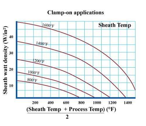
- In clamp-on applications, graph 1 (see below) shows the relationship between the watt density of the heating elements, the required operating temperature, and the maximum targeted sheath temperature.
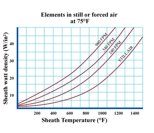
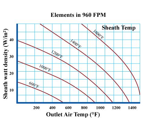
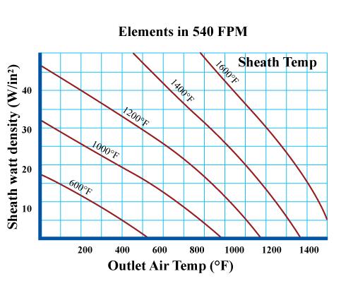
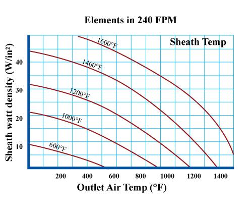
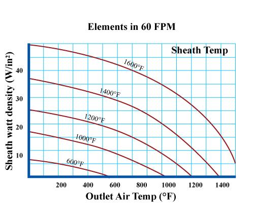
- When heating gases, the speed of the incoming gas and its outlet temperature should be considered in watt density calculations. Graphs 2, 3, 4 and 5 (seen below) show the relationship between the flow rate of air, its outlet temperature, the sheath temperature of the heating element selected and its corresponding watt density.
- When operating in vacuum, the watt density should be 20% to 30% lower. Because of the absence of air, heaters in vacuum mostly conduct heat through radiation.
Maximum Watt Density Ratings for Various Solutions for Tubular Water Heaters
| Solution | Maximum Watts/in2 | Max Operating Temperature (°F) |
| Acetic acid | 40 | 180 |
| Chromic acid | 40 | 180 |
| Citric acid | 23 | 180 |
| Nitric acid | 20-25 | 167 |
| Phosphoric acid | 25-28 | 180 |
| Alkaline solutions | 40 | 212 |
| Asphalt, tar | 4-10 | 200-500 |
| Bunker C fuel oil | 10 | 160 |
| Caustic soda 2% | 45 | 210 |
| Caustic soda 10% | 25 | 210 |
| Caustic soda 75% | 10 | 180 |
| Ethylene glycol | 30 | 300 |
| Fuel oil pre-heating | 9 | 180 |
| Gasoline | 20 | 300 |
| Machine oil, SAE 30 | 18 | 250 |
| Mineral oil | 16-26 | 200-400 |
| Molasses | 4-5 | 100 |
| Heat transfer oils | 12-20 | 500-650 |
| Vegetable oil | 30-50 | 400 |
| Degreasing solution | 23 | 275 |
| Hydraulic oil | 12-15 | 100 |
| Sodium phosphate | 40 | 212 |
| Trichlorethylene | 23 | 150 |
| Clean water | 55-80 | 212 |
| Deionized water | 60 | 212 |
| Demineralized water | 60 | 212 |

The watt density is determined with the following formula:
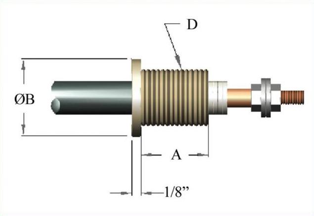
Crimped Fitting
| Part # | *Material | Used on | Thread Size | Dim. A | Dim. B |
| THF26C-B53 | Brass | 0.260″ | 1/2 – 20 | 17/32″ | 3/4″ |
| THF31C-B53 | Brass | 0.315″ | 1/2 – 20 | 17/32″ | 3/4″ |
| THF31C-B75 | Brass | 0.315″ | 5/8 – 18 | 3/4″ | 1″ |
| THF37C-B75 | Brass | 0.375″ | 5/8 – 18 | 3/4″ | 1″ |
| THF43C-B75 | Brass | 0.430″ | 5/8 – 18 | 3/4″ | 1″ |
| THF43C-B87 | Brass | 0.430″ | 5/8 – 18 | 7/8″ | 1″ |
*Fittings with different materials are available
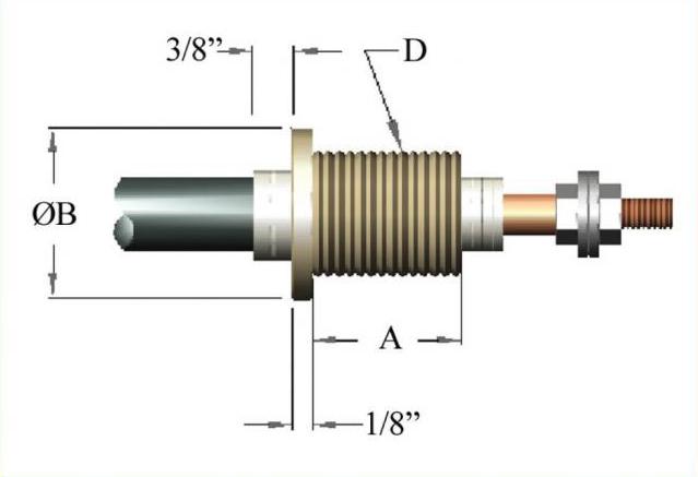
Welded Fitting
| Part # | *Material | Used on | Thread Size | Dim. A | Dim. B |
| THF26W-S53 | SS304 | 0.260″ | 1/2 – 20 | 17/32″ | 3/4″ |
| THF31W-S53 | SS304 | 0.315″ | 1/2 – 20 | 17/32″ | 3/4″ |
| THF31W-S75 | SS304 | 0.315″ | 5/8 – 18 | 3/4″ | 1″ |
| THF37W-S75 | SS304 | 0.375″ | 5/8 – 18 | 3/4″ | 1″ |
| THF43W-S75 | SS304 | 0.430″ | 5/8 – 18 | 3/4″ | 1″ |
| THF43W-S87 | SS304 | 0.430″ | 5/8 – 18 | 7/8″ | 1″ |
*Fittings with different materials are available
Brazed Fitting
| Part # | *Material | Used on | Thread Size | Dim. A | Dim. B |
| THF26B-B53 | Brass | 0.260″ | 1/2 – 20 | 17/32″ | 3/4″ |
| THF31B-B53 | Brass | 0.315″ | 1/2 – 20 | 17/32″ | 3/4″ |
| THF31B-B75 | Brass | 0.315″ | 5/8 – 18 | 3/4″ | 1″ |
| THF37B-B75 | Brass | 0.375″ | 5/8 – 18 | 3/4″ | 1″ |
| THF43B-B75 | Brass | 0.430″ | 5/8 – 18 | 3/4″ | 1″ |
| THF43B-B87 | Brass | 0.430″ | 5/8 – 18 | 7/8″ | 1″ |
*Fittings with different materials are available
“C” Clamp
| Part # | *Material | “C” |
| C15 | SS304 | 1.5″ |
| C20 | SS304 | 2″ |
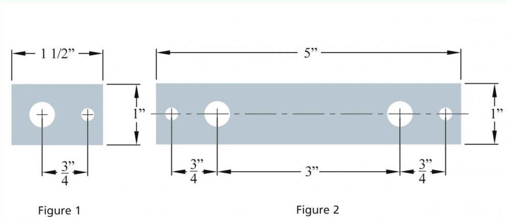
Mounting Bracket
| Part # | *Material | Fig. # |
| MB1000 | Steel | 1 |
| MB2000 | Steel | 2 |
Contact Us for tubular electric heaters with thermostat or electric tube heaters with thermostat.

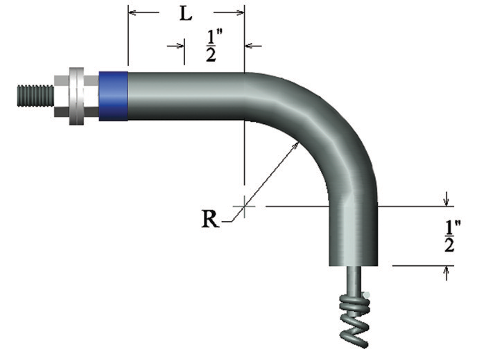
Bending
Annealed tubular heater can be bent. The inside radius of the bend should not be less than the recommended radii shown in the table below. For optimum results, bending should start from the center of a tubular heater and gradually move towards the ends. Care should be taken to ensure that the connection between the cold pin and the coil does not fall in the bent area. A minimum of 1/2″ clearance should separate this connection from the bend. The following sketch provides the necessary guidelines.
| Sheath Diameter (inches) | Minimum Factory Bend Radius (inches) | Minimum Field Bend Radius (inches) |
| 0.260 | 5/16 | 3/4 |
| 0.315 | 5/16 | 1 |
| 0.375 | 3/8 | 1 5/8 |
| 0.430 | 1/2 | 1 5/8 |
| 0.475 | 5/8 | 2 |
*For smaller bending radii please consult our factory
Standard Bending Formations
Re-compaction
During the process of bending industrial tubular heaters, the rock-hard MgO insulating material forms cracks, specially on sharp bends. These cracks and fractures are weak points that lead to overheating and failure in dielectric strength. This problem becomes more emphasized in high-watt or high-temperature conditions. In order to re-establish compactness and prevent failure, recompressing elements at bent locations becomes necessary.
Call Bucan today to learn more about Tubular Water Heater in Canada.

Mounting Tips of Finned? Tubular Heater
- Tubular heater expand when heated. At least 1% of element length should be considered as expansion and adequate clearance included in total design.
- When a tubular heater is attached to a surface, the middle clamp screws should be tightened completely. However, the end clamp screws should be tightened enough to hold the heater down and allow for expansion at the same time. This procedure will prevent the tubular heater from getting detached from the surface during the heating cycle.
- When tubular heater are placed in grooves, the groove depth should be less than the heater diameter by 0.008″- 0.010″, in order to ensure proper clamping.
- Insulating materials (if used) should never be in direct contact with heaters. An air gap should separate the heater sheath from the insulating material.
- Tubular heater electric terminals should not be placed in vacuum or heated zones.
Moisture Resisting Seals
The MgO insulating medium inside a tubular heater is highly hygroscopic and can absorb moisture from its terminal ends. Moisture resisting seals are barriers that resist or stop moisture and contamination.
Silicone Resin
This seal is a silicone-based resin that is applied to tubular heater terminal ends. The seal penetrates a short length of the MgO insulation and transforms it into a moisture and contamination resistant medium suitable for temperatures below 390°F.
RTV Seal
This is a silicone room temperature vulcanizing seal that can resist moisture and contamination for up to 450°F.
Epoxy Seal
This is a liquid resin which is thermally cured to reach solid state. This moisture barrier is adequate for temperatures up to 250°F.
FAQs

Are tubular heaters expensive to run?
The cost of operation varies by the size and power of the heater used.
Where should a tubular heater be placed?
All heaters should be placed in the location that produces the heat required for your application.
How long do tubular heaters last?
This is dependent on design and power cycle used.
How much electricity does a tubular heater use?
The power consumed is based on wattage and amperage.
What are the disadvantages of a tubular heater?
If a tubular heater is designed and suggested by a thermal designer, the disadvantages would be advised at the concept stage.